Welcome to the first in a series of tutorials covering basic studio wiring.
In this tutorial I’ll be looking at using and wiring the insert points of a mixing console. This question often crops up with clients and students alike and whilst many people are familiar with using signal processors (e.g. compressors, noise gates, graphic EQs etc.) on a computer armed with a Digital Audio Workstation (DAW) there is often some confusion about how to set up these devices in the analogue realm.
The digital world…
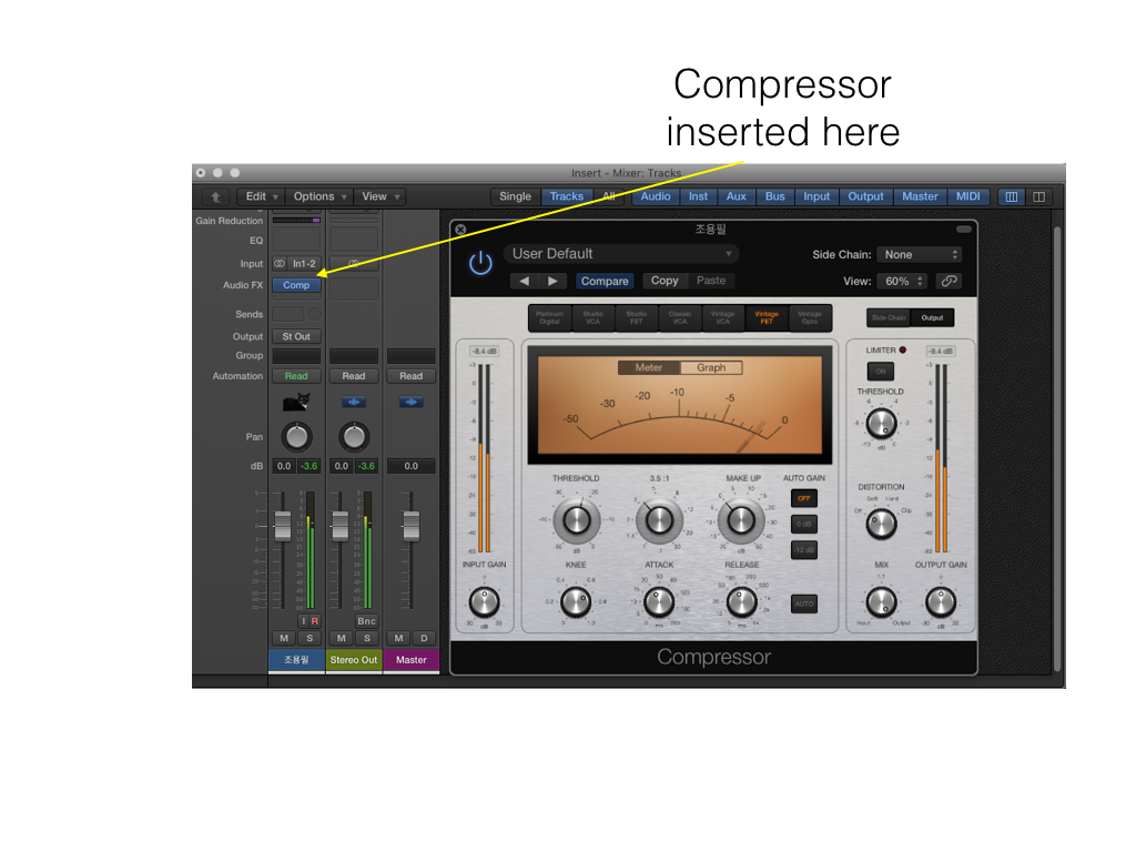
In a DAW environment, such as Logic, using signal processor plugins is fairly straightforward; you can simply click on the Audio FX tab on the mixer page and select the device you require from the drop down menu and away you go.
Analogue connections…
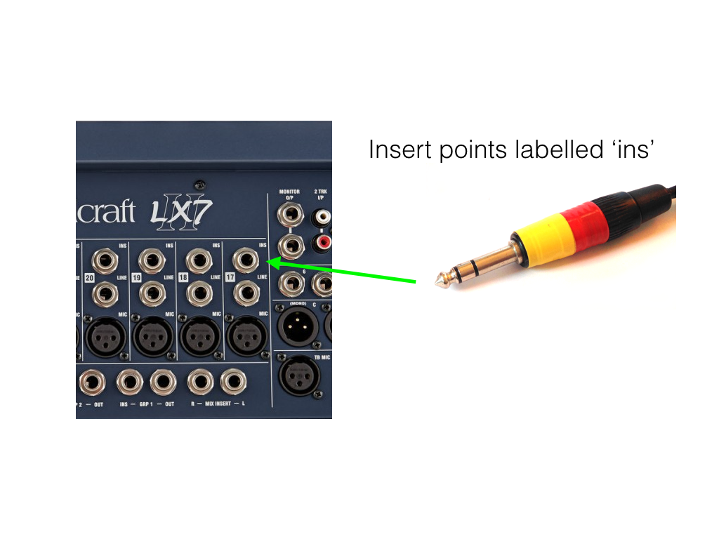
However, in the analogue world, whilst the signal path is the similar, the signal-processing device needs to be physically wired in via the mixing console’s insert points. These are commonly found on ¼ inch jack connectors on the rear panel of the mixer as illustrated in the image below.
Of key importance here is that when using inserts the signal is sent to and returned from the signal processor via a single cable. This is achieved using a specialist lead called an insert cable or ‘Y’ lead.
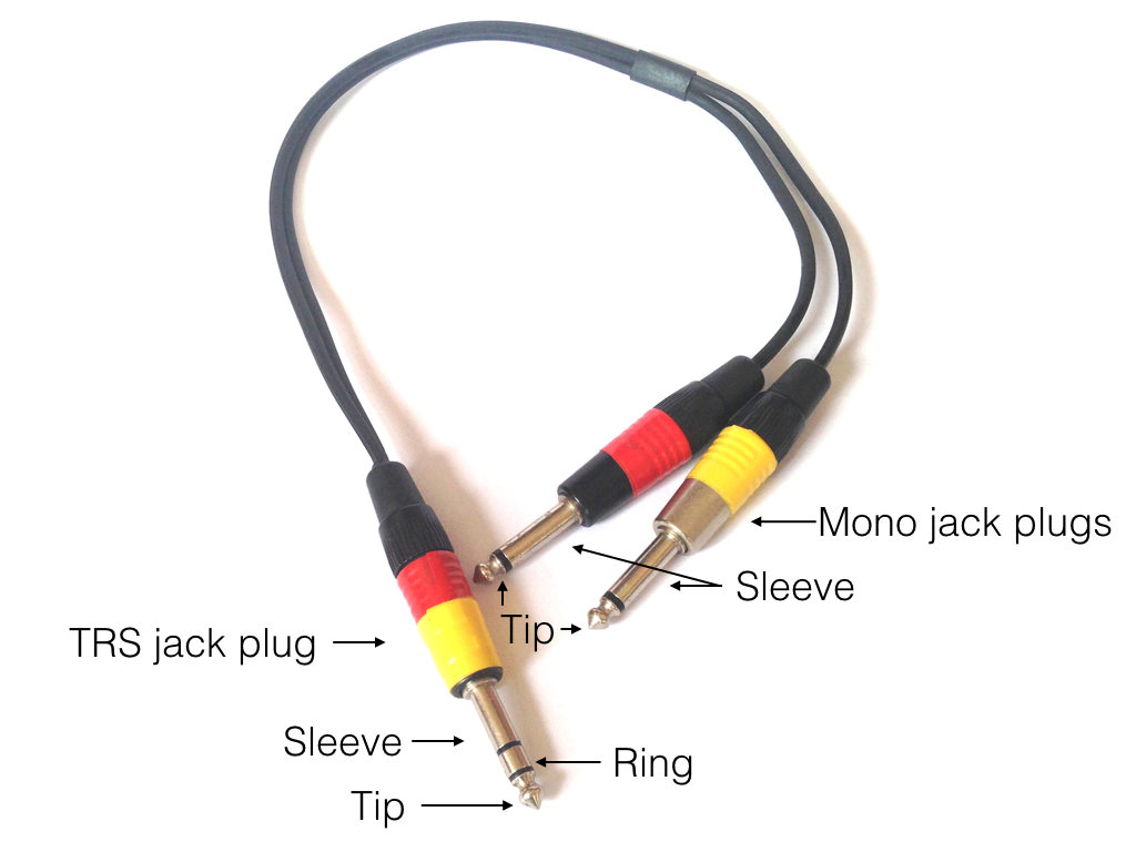
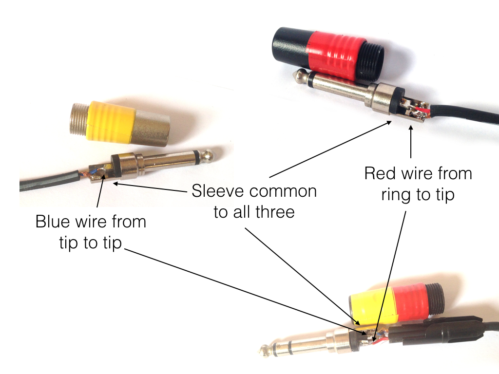
If we study the image above more closely you will see that on each end of the cable there are two different types of jack plug. The one with both the yellow and red coloured stripes is known as a TRS jack. This has three conductor points, namely the Tip, Ring and Sleeve, between which are two strips of insulating material. This design enables the jack plug to carry three discreet electrical signals. At the other end, the cable splits into two and is connected to two mono jack plugs with just tip and sleeve sections, separated by a single strip of insulating material.
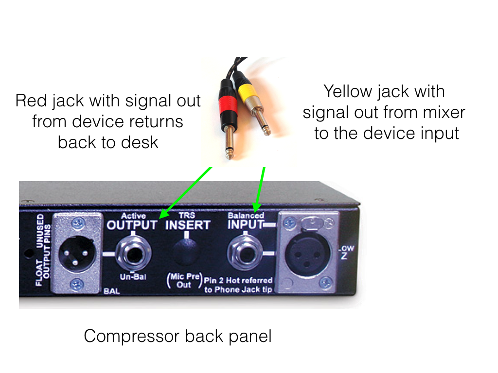
Now this is where it may get a little confusing… The tip of the TRS jack is used to send the signal from the mixing console to the signal processor. This is connected to the tip of the first mono jack (yellow).
The ring section of the TRS connector is wired to the tip of the second mono jack (red) and is used to return the signal back to the console from the output of the signal processor. Finally, a third screening wire connects all three sleeves, completes the circuit and offers a degree of protection from external electrical interference.
It should be noted that the colours used may change but the order on they appear on the TRS end of the plug will not. Also, whilst most insert leads are colour coded sometimes you may need to look inside the connector itself to identify which jack is the send and which is the return.
One last thing to consider…
If you’re using a patch bay with your insert points you should avoid “normalled” or “half normalled” connections for the signal processor’s input and output connections. Wiring in this way will cause a feedback loop where voltage is constantly passed through the signal processor, which could damage the unit over time, not a good idea!
There will be more on this in a forthcoming article on patch bays. In the meantime, if you have any further questions please get in touch via the contact page.
Copyright © Matthew Smyth 2015 | www.homestudiodoctor.co.uk